homepi+ Documentation
This document was originally created as technical documentation for the MES project in my MSc program.
Table of contents
- 1. Project description
- 2. Hardware description
- 3. Software description
- 4. Problems and solutions
- Why don’t you use the Authorization header?
- Why don’t you POST new configuration data instead of getting it?
- Why is this stateless and session less?
- Why was extending EtherCard-MDNS with DNS-SD support really required?
- Is there an Android client?
- Is there an iPhone client?
- Why does EtherCard-MDNS respond to queries like AAAA or HTTPS?
- Does EtherCard-MDNS have support for “pointers” in DNS labels?
- What bootloader does this system require?
- What features were present on the microprocessor implementation that have not made it here?
- 5. Conclusions
- A. Source code
- B. License
- C. Author’s information
- D. References
- E. Footnotes
1. Project description
homepi+ is an Arduino based implementation of a home appliance control system. It interfaces and communicates with various hardware devices in order to provide a single point of control for all of them. It is used to control all the electric and electronic equipment in my study room, from light fixtures to computers and laptops. The user interacts with the service using a simple web application which is accessible from any device which has a web browser, so pretty much any modern smart device, and can control it not only from the local network, but also from the larger Internet using a robust and secure security mechanism.
The project has a simple structure which is centred around an Arduino core which coordinates all peripherals. There are a series of adapters and interconnect mechanisms that are used to interface with the various physical devices that are to be controlled by the system, plus some external hardware that supplements the capabilities of the Arduino. Logically, the main program module is augmented by a series of libraries which provide specific functionality that the devices require. This document describes the in-depth structure and functionality of the system.
On a high level, the current capabilities of the system enable it to communicate and control the following hardware appliances:
-
Power-on, power-off, reset, and turn off functionality for a standard computer motherboard (particularly, it can control my standard desktop PC)
-
Power-on, power-off, and turn off functionality for a compatible notebook connected to a modified ThinkPad Ultra Dock (particularly, it is used to control my ThinkPad 25 laptop when docked in the previously mentioned equipment)
-
Output volume adjustment, brightness adjustment, and active source selection for an external computer screen (particularly, it is connected to my AOC U3277FWQ monitor)
-
Turn on, turn off, light intensity adjustment, mode adjustment, and colour adjustment for light bulbs (particularly, it controls the off-the-shelf Osram lightbulbs in my room)
-
Speaker system power on/off
-
AC equipment control via 5V relay modules (particularly, it toggles the light for my desk lamp)
-
Standby, source change for a Delock 18685 4K HDMI 2.0 switch
This paper is structured in a series of chapters that provide detailed information on the topic that each of them present:
-
Hardware description – an in-depth look on all the physical parts that link together to form this system
-
Software description – a detailed description of how all the software bits “talk” to each other and constitute the core of the system
-
Problems and solutions – a chapter structured in Q&A style that provides additional explanation regarding various choices that have been made when implementing this system and that have not been thoughtfully explored in the previous chapters
-
Conclusion – provides a high-level overview of the system and the results it achieves
-
Source code – this appendix features instructions on how to get started on replicating this project in your setup, plus information on how to explore this system in more detail
-
License – contains mentions about licenses, legal disclaimers, and regulatory information
2. Hardware description
The system employs an array of hardware devices in order to provide its functionality. The “brain” of the system is an Arduino Nano1, a board based on the popular ATmega3282 microcontroller manufactured by Microchip, which performs all the custom processing.
I chose this board in particular because it is cheap to procure, is easy to find, provides enough resources for this type of application, and benefits from a very mature and well-organized software stack that enables the developer to quickly get going compared to other boards, enabling him/her to concentrate on the actual task at hand, not to bury himself/herself with vast, overwhelming preparations of the device.
Another big factor that contributed to the decision of going along with this part is its breadboard friendliness, enabling easy interfacing and management with other integrated circuits and the possibility of rapid design altering.
A quick summary of the hardware capabilities of this board and its microcontroller is presented in the table in figure 1.
| Item | Specification |
|---|---|
| Microcontroller | ATmega328 (AVR architecture) |
| Operating voltage | 5V |
| Flash memory | 32KB |
| SRAM | 2KB |
| EEPROM | 1KB |
| Digital I/O Pins | 22 (6 of which are PWM capable, 8 are exclusive with the analogue pins) |
| Analogue IN Pins | 8 |
| DC Current per I/O Pins | 40 mA |
Figure 1. Specifications of the microcontroller.
In order to provide network connectivity, the Arduino Nano board is connected to an ENC28J603-based add-on module. This is a standalone Ethernet controller which interconnects via SPI, produced by Microchip. According to the manufacturer presentation, its intended applications include, among other, home control. Furthermore, this was chosen because it is low cost, easy to find, and provides a series of vital capabilities for this project, including a standard Ethernet port and bandwidth up to 10Mbps. Also, it includes a series of performance capabilities which help reduce the load on the MCU, and so the overall power usage of the system:
-
Internal DMA, which enables fast memory copy to/from the controlling device (the microcontroller)
-
Programmable wake-up on multiple packet types, including unicast, multicast, broadcast and Magic Packet®
-
Hardware assisted IP checksum
-
Programmable pattern matching within packet
Due to the small footprint of the Arduino Nano board, it does not expose all of the GPIO pins of the underlaying ATmega328 microcontroller, but only a limited subset of them. Because of the relatively big number of peripheral devices that need to interconnect with the microcontroller, and in order to anticipate future increases in the number of I/O pins required by expansion of the capabilities of the system, I decided to extend from the get-go the number of pins available by connecting shift registers to some of the existing pins. For this, I chose the Texas Instruments SN74HC5954 register, an 8-bit serial-in, parallel-out D-type register as it has a low acquisition cost, it is widely available via traditional retail channels, and allows cascading together the registers in the form of a chain, in order to minimize the pin requirements footprint on the microcontroller. The system exposes 2 such registers chained together.
In the next sections, a detailed description of each of the interconnect with the external devices to be controlled is presented. In the end, a detailed diagram shows how all the stuff links together to form this system.
Computer motherboard interfacing
Standard ATX5 computer motherboards all standardize around the use of a series of well documented header pins though which the computer can be powered on [1]. Traditionally, these pins are connected to a push button which is usually located on the computer case and can be used to power on/off, reset etc. the computer system.
For this system to be able to control the motherboard, interfacing with these set of pins is required. For this version of the system, I decided to interface with the power pin on the motherboard, which when pressed for a short time powers on/off the computer, and when long pressed it cuts off power to the system. Besides connecting the ground references of the motherboard and the Arduino together, by reading the ATX standard and motherboard documentation6, plus confirmation by measuring with the digital multimeter, I determined that the HIGH level of the motherboard is 3.3V, and the LOW level is 0V.
This naturally introduced a challenge, as the Arduino operates at 5V, while truly, most computing devices these days operate at 3.3V. A simple fix for this problem is to employ level shifters to convert between the two operating levels, but because of further requirements and desires for how some other equipment were to be linked to the system (2. Hardware description - Speakers), and also considering the flow of information in this subsystem (only the Arduino instructs the computer motherboard what to do), I decided to go with a device that electrically isolates the two systems, in the form of a Vishay 6N1367, a high speed optocoupler with transistor output.
Interfacing with the ThinkPad docking station
The ThinkPad Ultra Dock8 docking station allows a compatible laptop to connect to it and enhances its connectivity options by making available more ports, like video and USB, than are included standard with the notebook. It also features a button that is used to power the computer when it is docked, because the lid is closed, so the user does not have access to the laptop’s power button. The way the laptop and the docking station connect is via a proprietary parallel-like port located on the bottom of the computer.
Noting the presence of the power button on the dock, the process for determining an interconnect strategy was similar to when interfacing with the motherboard, although the challenge here is that this docking station is not a standard. Thus, its internal mode of operation is not published by Lenovo, and this meant opening it up and having a look at its internal PCB and devices. Despite this being the most challenging device I have ever opened, possessing an incredible number of mechanical pieces that are used to convert the force of your finger pushing the eject button to force that ‘kicks’ the laptop out of this dock, I decided that the strategy which is more likely to succeed is to solder wires to the push button that acts as the power button. The alternative to this that came to my mind was interfacing with the docking connector, yet I have not studied this further, and do not really know if the ‘power’ signal is transmitted straightforward via one of the pins, or somehow ‘encoded’ with other signals.
In the end, after some difficulty, as I was dealing with tiny SMD components, I soldered two wires to the button, one for providing a ground reference, and one for sending the signal from the Arduino. As was previously the case with the computer motherboard, I have experimentally determined that this docking station also operates at a 3.3V nominal level and decided to connect it via an optocoupler as well, which is to provide electrical isolation and logic level conversion.
Controlling a computer monitor
Monitors provide a lot of advanced functionality, but usually this is buried under a not-so-friendly OSD that the user has to navigate using, most of the times, cumbersome buttons located in all but convenient places on the shell of the display. Also, adjusting these parameters is impossible unless the user is in reach of the buttons, so if using the screen for a series of scenarios, like movie watching, this process becomes unnecessarily more complicated.
Fortunately, standards designers thought about this, and came up with a protocol that can be used to address these nuisances. Specifically, all commercially used video connectors, including DisplayPort, HDMI, DVI, and D-Sub DE-15 (VGA), have pins dedicated to issuing commands and querying capabilities of a monitor it connects to [2]. This is collectively referred to as DDC (Display Data Channel9). The way all of this is pulled together is that the monitor presents an I2C10 bus on those pins, and the receiving equipment, like the computer video card, can query the bus and look for “devices”11. The various devices there represent various protocols though which the monitor is able to communicate information. For example, in order to determine the supported modes (resolutions, colour information, refresh rate) of a particular screen, the video card will query address 0xA0 which provides the data in a format called EDID (Extended Display Identification Data12). All monitors have their “optimal” mode (aka “recommended resolution”) determined by the display device using this method.
Another device that resides on the monitor I2C bus is the Display Data Channel Command Interface13, which is located at address 0x51. This accepts commands issued using the DDC/CI protocol. The commands are described in the MCCS (Monitor control command set14) of this standard and are called VCPs (virtual control panels). By issuing a DDC/CI command with a particular VCP, one can read or set its value [3].
Although VCPs are standard, monitors are not required by the standard to implement all of them. Thus, I had to determine what VCPs that might interest me are available on my monitor. Specifically, I was interested whether my monitor’s brightness, volume level on its 3.5mm output jack and active source could be changed using DDC/CI. Unfortunately, this is needlessly complicated, because modern operating system desktop environments (like Windows, GNOME, KDE, macOS etc) still do not offer quick controls for desktop monitors. For example, pressing the brightness keys on my laptop only toggles the internal display’s parameters (as a side note, the laptop display is connected via embedded DisplayPort and uses a totally different protocol for adjusting these parameters). There are no controls in the UI of these desktop environments for adjusting these, although all operating systems provide APIs to do so programmatically, besides sometimes even the video driver offering such APIs. It is just that the APIs are not exposed in the form of system controls to the users, this role being left to be filled in by third party applications.
On GNU/Linux, one such application is ddccontrol15. This is a comprehensive utility that allows interacting with DDC/CI and is what I used to determine that indeed, my particular monitor model supports the VCPs I was interested. On Windows, a similar GUI utility is NirSoft ControlMyMonitor16.
What was left was to physically connect the Arduino to the monitor somehow, specifically to the SDA, and SCL lines of the I2C bus. For this, I decided to sacrifice a video input I was not using anyway, which is the VGA input entry (my monitor has a resolution of 3840x2160, while VGA supports up to 1920x1080 anyway). Technically, one does not have to really sacrifice the whole input port for this operation, but just the SDA, and SCL pins in the connector. The reason for this is that the I2C bus was introduced on monitors after the VGA standard was invented and went in use for video connections. Historically, VGA used two pins whose 4 possible values indicated what mode the display supports, but as you realize, this is quite limited in the amount of information you can tell, so more advanced solutions, like DDC/CI, were later adopted. Also, these pins indicate to the video adapter what capabilities the monitor has, but the video card is free to send whatever signal it pleases via the video pins (although do note that, in the past, this could damage CRTs, as the video signal controls the movement of the internal ray tube that produced the image).
So, one could technically slice a VGA cable, and connect the I2C pins to the Arduino, and the rest of the pins to a video adapter on the computer. What is left to do in order to properly display an image at the native resolution (as without EDID available, video cards usually default to outputting the standard 640x480 VGA resolution17 all monitors having a VGA connector must support) is to tell the video adapter to use custom EDID data you have previously extracted from the monitor when normally connected (this is called EDID injection). An example of such a patched VGA cable is shown in the next figure.
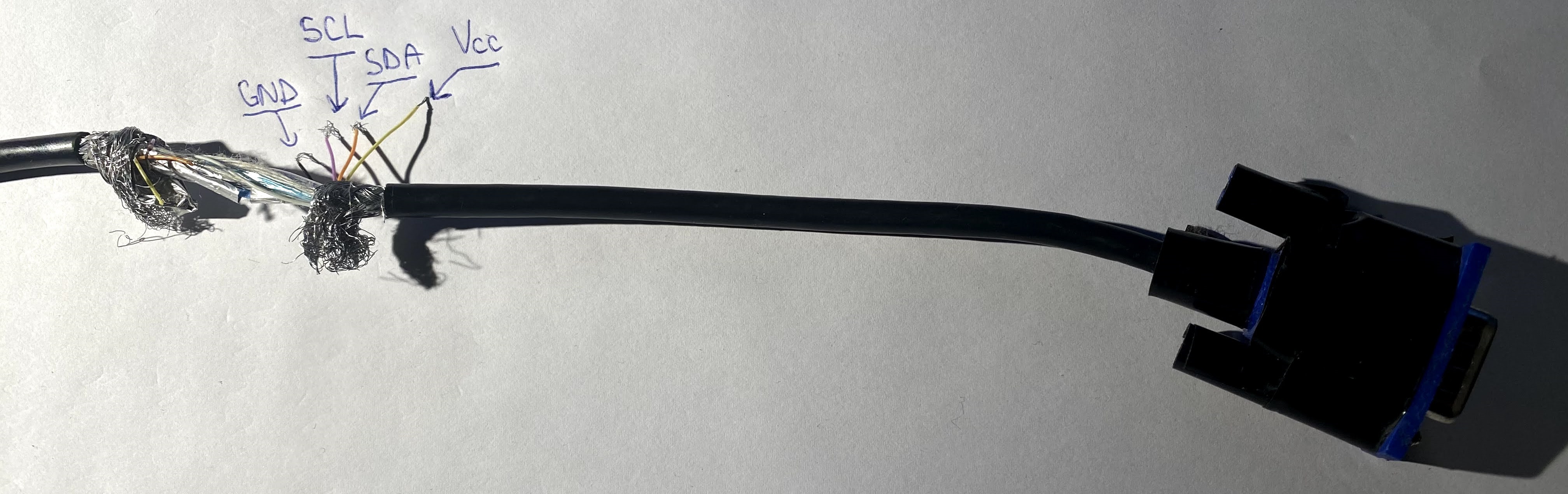 Figure 2. Example of patched VGA cable.
In the end, I connected the ground reference of the monitor with the ground on the Arduino, plus the SDA, and SCL pins from the VGA port to the Arduino. But that is not the end of the road. The way the I2C bus on the monitor works is that it is powered by the receiving device, i.e., the video card or, in the case of this system, the Arduino. The reason for this is so that the receiving device can query the capabilities of a monitor and even configure it even when the monitor is powered off, enabling advanced scenarios. So, I also connected the 5V line from the VGA cable to the power supply I use to power the system.
Lightbulb control
For the lightning in my room, I recently switched to a couple of “dumb-smart” lightbulbs. I call them “dumb-smart” because they are more advanced than the traditional lightbulb that you just insert in the socket and use a mechanical switch to turn on/off, but not fully smart, in that you could control them directly via some specific protocol over an IP network, for example. These are a very cheap middle ground to the prohibitively expensive truly smart offerings like Philips Hue18. The models I have are produced by Osram, and come in standard E27, and E14 Edison socket screw19 variants. The way these work is that they come with a remote control that sends them “codes” using infrared light.
Nothing fancy was necessary here, as interfacing with them meant simply dedicating a simple, standard IR LED for each of the bulbs, and connecting that to one of the Arduino pins. For reasons not that obvious now, but that will be thoughtfully explained later in the software description section of this document (3. Software description - Processing updates), I have connected these in an unconventional way: the anodes (plus) of the LEDs are connected together to an Arduino pin, and separately the cathodes (minus) each to a pin on the shift registers. This, of course, via a current limiting resistor.
What was left to do was to determine the “codes” of the infrared remote. “Codes” is the short way of saying the sequence of pulses and its timing that the LED has to produce in order for the receiving device to understand it as a certain command and act accordingly. Naturally, there are various ways of encoding these pulses, so a host of protocols each operating a bit different, but with a similar principle. For this step, I used a Vishay TSOP3483820 IR receiver that I connected to an Arduino and used a software IR library to capture the pulses from the remote and save them for subsequently sending them using the same library to my custom IR LEDs in this system. This allowed me not only to determine the actual patterns the remote produces, but also the actual protocol that is in use, which for these devices is the NEC Infrared Transmission Protocol21.
Speakers
This part is very specific to the equipment I have in use. Speakers come in a variety of forms and configurations, some are passive ones that have to be plugged into an amplifier though which you control them, so supposedly one needs to interface with that in order to control it, while some, especially the likes of portable, or lower powered speakers, have a built-in amplifier and a few controls for powering them, for example. My setup is, for the moment, in the latter camp, and I have a pair of speakers (Nokia Play 36022) that connect via a 3.5mm jack to my monitor via a headphone amplifier (Fiio A123). These speakers each have a button on their back that when long pressed, powers them on or off. Similar to how I connected to the ThinkPad dock, I had to take apart the speakers, and soldered wires to the pins of the power button. This was extremely complicated with the equipment I had because everything was obscenely tiny. For connecting to the Arduino, I tied together the two grounds of the speakers, and the two control wires, and wired those to the Arduino.
In fact, they are not connected directly to the Arduino. The speakers also use 3.3V logic, so they are again connected via optocouplers. But these are the true reason I went with using optocouplers: audio, especially audio sent though analogue channels, is very sensitive to all sorts of electrical signals that may leak on the audio cables, like ground loops24, unintended DC offsets etc. As I wanted to completely negate the electrical “influence” the Arduino might assert to the audio, I decided to keep the circuits galvanically separated, so the optocouplers were the natural choice, besides providing the necessary logic level conversion.
Other devices
As mentioned in the intro, there is code, and a hardware configuration was made to support controlling a Delock 18685 HDMI switch25. In the end, I scraped this out of my configuration, not due to limitations with this project, but due to the limitations of the HDMI switch itself (in my setup, it introduced a DC offset to the audio signal, for some reason).
Furthermore, I deemed this switch unnecessary for my setup after all (specifically, another negative aspect is that when you switch sources, the source you switch away from does not see a monitor connected to it anymore; in practice, if you connect a computer to this switch and switch away from it, the OS will detect the monitor as unplugged and rearrange all your windows on the remaining monitors and basically ruin your whole desktop).
This switch is controlled via an IR remote as well, and coincidentally, it uses the same protocol and even some of the same codes as the Osram light bulbs.
The system is also connected to a module with 2 relays that are controlled by 5V logic. To control each of the relays, a control pin is provided for each, which must be connected to the microcontroller. In this system, the relay is connected to two of the pins on the shift registers.
System diagram
This subsection provides an in-depth overview of how every component is physically connected to the system. In the following figure, an in-depth overview of the system architecture is presented.
This diagram was generated using the open-source Fritzing26 software. Unfortunately, one has to manually compile it if they want to use it for free, as pre-compiled Windows binaries are now locked behind a paywall (mandatory “donation”). Also, a quick note regarding the diagram: as I was unable to find a part for the 6N136 optocoupler in Fritzing’s parts library, I used an IC with a similar number of pins, TL072, to represent it on the breadboard. These ICs are by no means compatible or interchangeable. TL072 (which is an operational amplifier, actually) is just a placeholder due to technical limitations, you should still make sure to use a proper 6N136 optocoupler if you intend to recreate this layout.
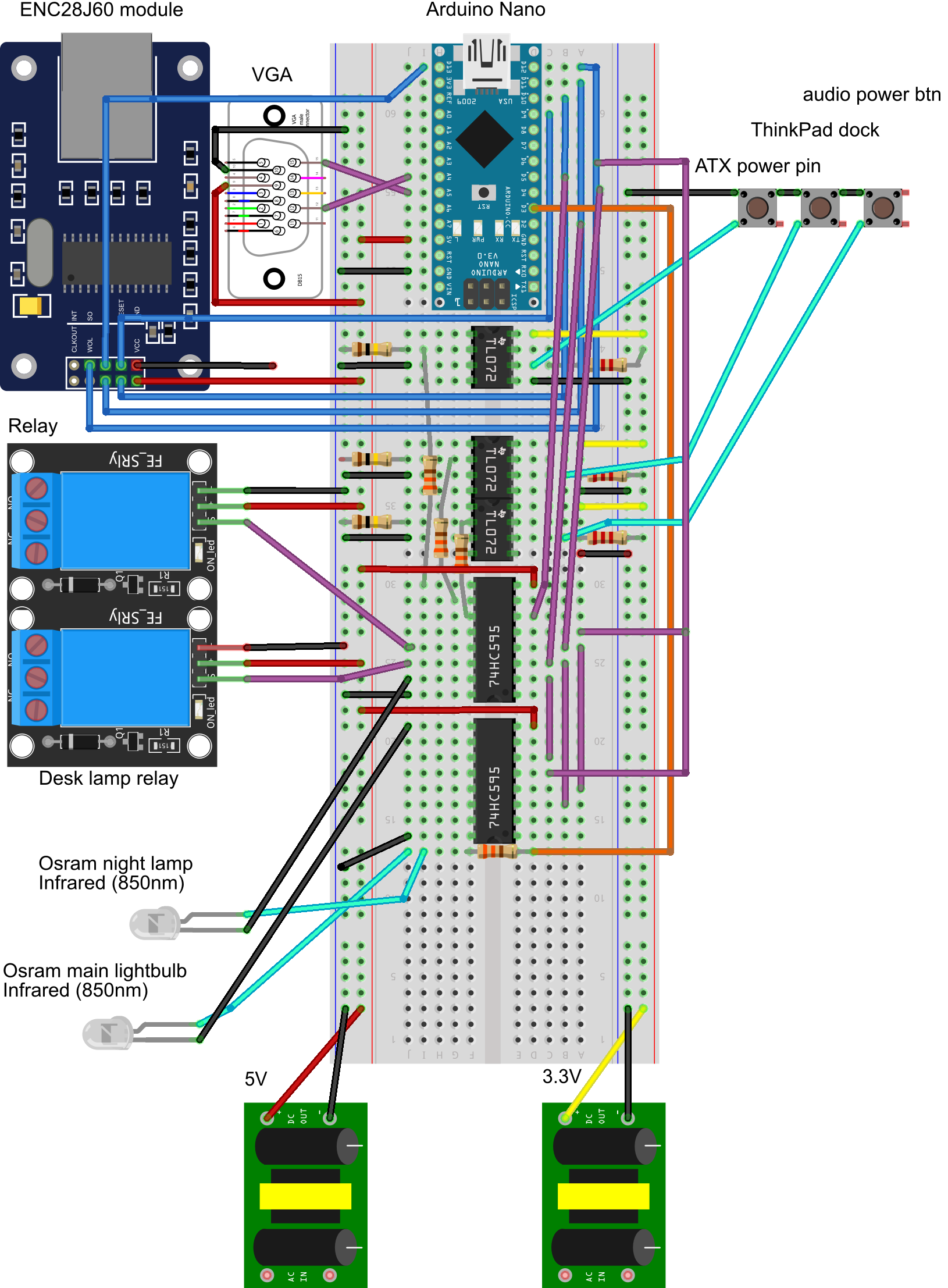
Figure 3. System schematic.
3. Software description
As important as hardware preparations are, these cannot exist alone without software to take advantage of them.
The software side of this project explains why the project is called homepi+, and specifically why “plus”. Initially, part of the functionality accomplished by this system was taken care of by an architecturally different system built around a Raspberry Pi. This alternative, improved version was born out of the need to get rid of a couple of problems which the software side of the previous project was responsible of:
-
IR LED control is cumbersome in GNU/Linux; there is a LIRC27 library, but it has some usage quirks which made its initial deployment and subsequent usage particularly cumbersome; for example, some issue always prevents correct sending of IR signals; unfortunately, due to the sheer complexity of the underlaying system, it is hard to investigate the root of the problem without extensive knowledge of the whole system framework
-
Similarly, the standard mDNS daemon that is used by most Linux distributions, avahi, is slow sometimes, at least in my configuration, again, do not know exactly why
-
Configuring the Apache28 web server is cumbersome at times, so I had switched to nginx29 eventually, but again, why do I have to waste configuring software instead of working on the system’s functionality?
Born out of the desire to go a level lower, where I have more control over how things work together, I decided to attempt implementing the ideas of the original project on an MCU, and thus the “plus” version was born. The “homepi” part of the name does not make much sense from the current point of view of the project but serves as a reminder of the development history of the system.
To ease developing, especially the initial getting started phase, I decided to use the standard Arduino software framework30 for development. Of course, there is a slight initial overhead of making everything ‘object-oriented’ and classful, as this means writing C++, but this is offset by the rapid prototyping, plus the fact that a subsequent gradual transition to pure C should not be that difficult.
I have worked with avr-gcc, avrdude and writing pure C code before, and besides learning, there is not really any point in ORing a PORT when you want to set a pin instead of using digitalWrite, especially at the beginning when the focus is on getting a rough prototype working, rather then ironing out all the possible optimizations. The microcontroller has plenty of resources for what this project attempts, despite it previously running on at least 100 times more powerful computer before, which it did not really benefit from.
The software stack is centred around a typical main Arduino module, or sketch as it is called in the specific nomenclature. Plugged into this module are a series of libraries that each take care of a part of the whole system, while everything is glued together by the main loop of the program.
The project employs a series of security mechanism that ensures the reliability and safe operation of the application. These will be described in the subsequent subsections of this document.
Libraries
The libraries used for this project are the following:
-
Wire31, from the standard Arduino library – provides I2C communication capabilities
-
Cryptosuite32 – provides an implementation of the SHA256 algorithm
-
EtherCard33 – library for using the ENC28J60 module
-
EtherCard-MDNS34 – library that configures mDNS and DNS-SD capabilities (depends on EtherCard)
-
IRLib235 – provides IR protocol implementations
-
TOTP-Arduino36 – library that is used to generate TOTP codes (depends on Cryptosuite)
Detailed information about the technical role of the libraries is provided thoughout the rest of this chapter, while licensing information can be found in the annex at the end of this document.
In order to preserve the status of each of the libraries at the time the system has been put together, and also provide slight patches that mostly enable them to work with the custom folder structure of the project, I have forked each of them on my personal Git.
Start up
At system start up, the standard “setup” Arduino function is invoked. This mainly accomplishes a couple of roles:
-
Sets the initial state of all the internal variables, plus initial pin values.
-
Outputs a series of commands to “synchronize” with the external world. As an example, the Osram light bulbs always turn on after a power outage. As this is rarely required, since this may happen during the night or when the user is away, and considering that after a power outage the Arduino is restarted, the library turns off all light bulbs at start up.
-
Initializes the libraries used throughout the project.
Of note here is how the IP address of the device is determined. Although not necessary by any means, I always prefer to assign a static IP address to these types of devices instead of doing it though DHCP [4] (Dynamic Host Configuration Protocol37). The approach has a couple of advantages:
-
Since the system is going to be fixed, always powered, and connected to a LAN (local area network), there is no point in issuing a lease and renewing it, since that is virtually the same as having a static IP, only that you can establish the address using the interface of the DHCP server, instead of in the code
-
Also, a static IP makes it easier to debug it by accessing the interface directly via the IP address, or sending ICMP packets (pinging) the IP, in those cases when the DHCP server may be unavailable.
-
The DHCP portion of EtherCard can be disabled and not linked at compile time, freeing up valuable resources.
Also, at start up, after the synchronization phase, the system checks for LAN connectivity indefinitely before proceeding, as the functionality is entirely controlled via the web interface.
Besides thoughtful code checking at design and compile time, this project employs another security mechanism in order to prevent the system going into an undefined state: a 15-second timeout is enabled on the code using the built-in watchdog. The watchdog is an internal counter of the microcontroller. If reset does not happen in less than the specified timeout value, the microcontroller is rebooted. This ensures that any hang ups due to bugs in the code do not last more than 15 seconds. More conservative values can be applied here, but of course this limits the number of operations you can do in the time between watchdog resets, which ideally should be once per main loop execution, in order to make subsequent diagnosis somewhat meaningful.
Main loop
After the setup phase, the main program loop begins. Here, the system issues a non-blocking call to the EtherCard library that polls whether new packets have been received. This repeats until new packets are indeed received. Of note is the fact that the EtherCard library is configured to “notify”38 for new packets only when they arrive on TCP port 80, the standard HTTP port. All other packets are silently discarded (actually, a small subset of them is treated by a separate library; see 3. Software description - Accessing the service).
The non-blocking nature means that the microcontroller is free to execute other tasks as well, it does not become “free” only when there is some packet waiting in the queue to be processed. At the moment, the only other thing the main loop does in this “free” time is to check whether a predefined number of minutes have passed since the system has been started, and if true, the system is soft reseted. This is another security precaution that tries to prevent the effects of any memory corruption that may happen during operation, but it will probably be disabled after more real use testing with the system is done.
So, when the main loop is “notified” of a new packet, it means incoming HTTP traffic for the system to process. Further communication is done via a simple web page that acts like as the interface with the user. Besides HTTP being a stateless protocol, the application does not model a state system internally. All user agents39 talking with the application via HTTP have the potential of modifying a singular, global, unique set of internal variables. In other words, there are no sessions when using this application, and thus there is no need for and the application does not use technologies for identifying a user agent in time, like cookies40. The only client-side41 technologies required by this application are a web browser capable of rendering HTML5 content, with JavaScript enabled.
Securing access
On the local area network, access to the application is permitted for any connecting user agent. This model could not be applied to the generic Internet though, as that would have meant that anyone knowing the address of this service could potentially connect to it unhinderedly and alter the state of the controlled devices. A secure mechanism to provide access to the application from the public Internet was necessary, i.e., a low overhead method for authenticating the user agent was required.
Initially, naturally, I thought about HTTPS, but I quickly realized that this would be tough to downright impossible to implement due to various considerations:
-
The horsepower of the microcontroller simply does not allow neither the kind of computations secure HTTP connections require, nor the memory footprint of such an implementation; literally, memory is a big issue that makes this virtually impossible to pull off with an on-chip only solution.
-
Almost no proof-of-concept code is available, which would considerably slow down the implementation.
-
HTTPS “communication” begins with an asymmetric42 phase: for it to work, each web site must provide the other party with its public key; this is achieved via the use of a certificate; besides the burden of obtaining one (there are free services available, like the well-known Let’s Encrypt43, fortunately), that also has to be renewed periodically, which means the MCU has to be taken offline and flashed with the new data from time to time, as the certificate would most likely be stored in the program memory. A workaround could be to generate a self-signed certificate at each run, but because the authority of such a certificate will not be a descendent of one of the trusted certification authorities from the user agent’s local certificate store, the browser would pop up “scary” warnings about the connection being potentially shady, and that simply slows down the whole process for no reason.
Furthermore, HTTPS is not really required, as the page and its data do not really have to travel encrypted, as these do not really contain data that is that “private” (the data represents only commands issued to the controlled devices, or their current state). What is really required is a mechanism that allows authenticating the requesting user agent, not encrypting the entire communication.
Also, HTTPS would not really solve the actual issue. Even if traffic would be made over HTTPS, so in-transit data is encrypted, there is still the need to somehow authenticate the user agent. For this, a static password may be employed, but the danger is that, should it become compromised, then any actor can impersonate a legitimate user and attempt communication with the application. Also, a compromised password is hard to change, probably requiring down time, since such a password would likely be written in the program memory of the microcontroller, so a reflash of the MCU would most likely be required.
Having decided on this aspect, I shifted my thinking towards a simpler approach based on symmetric cryptography44. Thus, the authentication key, or “password”, should be sent along with the request, from the user agent to the server. But again, this makes it trivially hard to exploit with a static password, because it allows for replay attacks45, as mentioned above. Thus, I decided that the password should be changed frequently, and without a recognizable pattern, so that the risk is reduced. For this, I remembered about a well-known protocol that is used by most services that employ 2-factor authentication: the time-based one-time password algorithm46 (TOTP).
There is extensive documentation on TOTP and its ancestors throughout various RFCs [5] that describe it thoughtfully.
In short, the way this works is straightforward:
-
A key is chosen and shared with all participating parties
-
The key is encrypted using one of a few select algorithms (I used SHA-25647 [6] in my implementation; any algorithm would work, but it is limited to a specific subset by the TOTP standard)
-
The encryption is repeated several times proportional to the current date and time; due to unsynchronized clocks, time is sampled in bigger intervals; for my application, I chose to sample every 30 seconds
-
The resulting string is truncated to a certain number of digits (I chose 8 for my application) and represents the “password” that the user agent will send to the server
Because the current time is used to “seed” the algorithm, the resulting password changes as time passes. Also, even though the password is based on a shared key, as the key gets encrypted with a powerful algorithm, and is also truncated, an attacker cannot recover the original shared key, which never travels on the wire.
With this being the case, the generated “password” is still the same during 30-second time intervals, introducing a new limitation, in that a man-in-the-middle attack48 could be employed, where the “password” is captured in transit and reused during the time period it is valid. This could be mitigated in various ways, like limiting each use of a code to one time, i.e. the code is valid for a single request, and then, even though during the valid time window, is nevertheless rejected by the server (this completely reduces the possibility of replay attacks, but may still allow an attacker to intercept the communication, tamper it, and forward that to the server instead of the original message; because the data in transit is not encrypted, changing it in a meaningful way is very easy).
I employed a similar mitigation, in that the application will only allow up to three requests with a valid code during the valid time window of a particular code: the first time for initially obtaining the web page, the second time for allowing new data to be uploaded to the server, and the third time for the confirmation page to be sent back to the user agent. This reduces the time in which an attack could be performed even further, compared to the original 30-second window, although it is still not completely non-vulnerable. Unfortunately, this is simply a limitation of this technique, but considering the very low implementation overhead and extremely light resource usage, at least compared to more “complete” solutions, plus taking into account the intended functionality and the robust security it actually provides, I think this is better than plainly showing the web page when requested from the public Internet. Of course, this coupled with HTTPS would be optimal, but as it has been said, not really a possibility on this MCU.
To generate the TOTP codes on the client, an “authenticator” app can be used, like Matt Rubin’s Authenticator49 app available on the Apple App Store (numerous alternatives are available for most operating systems, and writing a simple client is equally trivial; Google Authenticator does not work because it only supports SHA-1 with 6-digit codes, while I used SHA-256 with 8-digit codes, which is still a valid choice according to the TOTP specification).
Communication details
Having established how external communication is handled, we can proceed to explaining how actual communication is performed; the application responds differently depending on the requested “path” in a GET request. For this explanation, let us consider the TOTP password corresponding to the time of the request as being 12345678, the local IP of the system being 192.168.0.24, the public IP of the LAN being 8.8.8.8, and that the NAT box forwards incoming traffic on TCP port 8888 on address 8.8.8.8 to TCP port 80 and local address 192.168.0.24. Thus, the application can work with GET requests for the following paths:
- / – For requests to an URL like http://192.168.0.24/, the main page of the application will be served; this contains a form where the user will see the current state of the controlled devices and can change their state; a representation of this interface is shown in the following figure. When requesting this path using the public IP of the LAN, like http://8.8.8.8:8888/, the user agent will receive a small stub page that will prompt (using JavaScript) for a TOTP password. Suppose the user provides the TOTP code 87654321, then a new request is made to address http://8.8.8.8:8888/87654321.
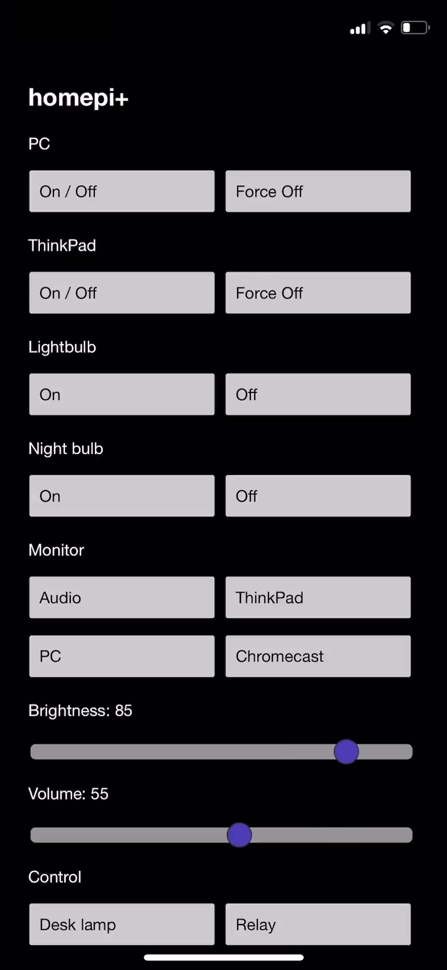
Figure 4. Main application interface.
-
/12345678 – For requests originating from the public Internet (so, to address http://8.8.8.8:8888/12345678), for the first three requests with such a code, the main page of the application will be served; otherwise, a small stub will again request a TOTP code from the user; any code is invalid until a new 30-second time window begins
-
/?parameters – This works only for requests originating from the local LAN and is used to upload new configuration data to the server; the exact parameters and their values can be obtained by exploring the source of the page sent by the server (a valid example could be “ra=0&vol=100&br=10&r1=on”); the response will redirect the user agent to the main page
-
/12345678?parameters – This is the same as the above but works from the public Internet; the difference is that the TOTP code is present in the request, and is used to authenticate the request; similar to requesting the main page, this works only for the first three requests with that code during its window; for subsequent requests, a new code will be requested from the user
-
Any other combination of parameters will make the server behave similarly as to when / is requested
To determine whether the request comes from the public Internet or the local LAN, a trivial technique is to check whether the source IP of the received packet is the network gateway, as that is usually also the NAT box; that is the current implementation and works for most use cases. For a more precise implementation, the value of the ‘host’ parameter in the HTTP header could be checked against a set of expected values for when the packet arrives from an external IP.
Serving the main page
To serve the main page, as is the case with most strings in this application, its contents is stored in the program memory. As it is too large to fit in EtherCards’s buffer (this is configurable and is set to the minimum dimension allowed by the library, in order to eat as few dynamic memory as possible), the page is sent back in chunks, and only the last chunk is accompanied by the TCP FIN flag50, which tells the receiving end (the user agent) that the transmission is complete. Each chunk’s contents and size are determined dynamically, at run time.
This all works well, but there was also the need to customize the initial values of the form in the sent HTML to the current values reported by the controlled devices (for example, set the monitor brightness slider to the current brightness value reported by the monitor). To achieve this, the trivial solution is to modify the sending buffer after the specific chunk is copied from the program memory, but before it is sent. This presents several challenges, like having to evaluate beforehand the length of the fill-in data in order to avoid overflowing the buffer, determining the right chunk where the insertion has to be performed etc. To avoid this, I decided to set initial values using JavaScript on page load on the client side, and only generate the script section of HTML responsible for this dynamically, allowing the variable data to be more compact and easier to fill in in the code on the server.
Processing updates
When a suitable “request” is received, it is parsed, and from it the devices and associated new configuration are determined. Then, specific code snippets are executed, which alter the state of the controlled devices.
As stated in the previous section, I owe you an explanation over why the IR LEDs have their anodes connected together, instead of the more common cathode connection style. This is required because the library used to send IR codes uses a single, hard coded pin (pin 3) for transmitting the codes. This means that in order to control multiple LEDs, one must pull low the cathode of the LED it wants to control, leaving all the others high or in a high impedance state (not connected). Thus, what I control in software when issuing an IR command is the logic level of each of the anodes of the LEDs and issue the command on the same digital pin regardless of the LED I intend to fire up.
While this may seem unnatural at first, it is required due to how the library is designed, but it also is a very advantageous design, because it actually uses only one digital I/O pin, instead of one for each IR LED one wants to control. Even if the library allowed for having separate instance each on its own pin, one would still have to use the digital I/O pins to do so; operation via pins on the shift register is not possible. All in all, I strongly believe that this design, even though very different to the logic one would naturally envision, is superior and a better solution to this problem.
Accessing the service
Although IP address provide a (somewhat) unique way of locating a certain resource, for humans, memorizing IP addresses is hard. Furthermore, a new user on a network cannot really discover services on that network if those services only expose an IP address, as the user would have to manually attempt communication with each address on the local subnet, on a set of predefined ports, and see which attempts succeed. What if the local subnet is large? What if the service the user is looking for does not run on one of the ports attempted, or what if the user does not even know the port that the service he/she is looking for is supposed to run on?
To mitigate this, a series of protocols have been proposed though various RFCs and adopted as standards. This work towards the goal of zeroconf, which implies that network devices in a LAN should be able to know of the presence of each other without any user intervention and/or configuration.
Even for the problem of choosing an IP address, there have been standards defined that allow hosts to assign themselves an IP address and describe the process to do so [7]. But for this system, this is not really of much use, as I wanted something even more friendly than that (an IP address is still an IP address).
To start off, it would be easier if the user could type a domain name, an actual web address in the browser, and get to the service, instead of the IP. For example, this system can be reached, from the local network, by visiting http://homepi.local.
The way this works is by leveraging the Multicast DNS [8] (multicast domain name system51) protocol (mDNS). The idea is straightforward: mDNS aware resolvers (on Windows, the system resolver is mDNS aware since Windows 10, while Apple’s Bonjour implementation is available for older OS releases) will attempt to resolve certain reserved domain names (like ones ending in “.local”) by issuing standard DNS [9] (domain name system52) A type query packets to the multicast address 224.0.0.251 of the local subnet, on UDP port 5353. As 224.0.0.251 is not routable and is in the local subnetwork range53, traffic to this address is forwarded on all interfaces, so basically to all hosts in the local subnet. Then, it is the responsibility of each host to inspect the packet, determine whether a name it recognizes is contained in the question, and answer with a DNS response packet containing its IP address. The DNS protocol is well established, low overhead and the de facto standard for IP to domain and domain to IP resolution. Providing that one picks a unique name for its service, a single host should respond to a request for a particular domain, and the browser will be able to resolve that domain to an IP. This has the advantage that it is decentralized, bypassing the DNS server provided during network autoconfiguration using DHCP, for example. This means that the user of the network does not have to do any additional configuration, which in most cases he/she would not be able to do anyway (LANs usually use public/ISP’s DNS servers which the user has no access to configure).
Besides that, for a true zeroconf implementation, the service should be truly discoverable. Suppose we deploy this system in multiple rooms of the house: how do you manage the domain names? Sure, with a few rooms and a predictable naming scheme, something like http://bedroom.local, and http://livingroom.local/ is totally feasible, but what if the user does not really know which “rooms” have this system deployed, i.e., the topology of this home? Is he/she supposed to guess the domain names, trying a descriptor he/she finds fit for each of the rooms in the house? This is not very efficient, and in fact, it is time consuming. To work around this issue, another protocol has been implemented: DNS-SD [10] (domain name system service discovery54). This is well known already by most users: that is how your phone can look for and discover Chromecast devices, or your network printer, on the local network, for example.
The way DNS-SD works is straightforward: like mDNS, it builds on the foundation of DNS, by using DNS packets as well. Also, it works on the same address and port as mDNS, but it can also function in unicast mode on the same port (which means requests can be specifically addressed to a particular host to resolve them). In order to identify details of a particular instance of a service on the network, a chain of events like the one described below may be employed by a client:
-
The client should issue a PTR query for _services._dns-sd._udp.local. All hosts are expected to answer to this request with the name of the service they advertise.
-
To explore a particular service (for example, homepi’s service type is _homepivalinet._tcp – service names are expected to be made out of two DNS labels that begin with an underscore, the last one being the protocol used: TCP, or UDP, in most cases), the client should issue a PTR query for that service. Hosts providing that service are expected to reply.
-
The replies will all be differentiated by having a different instance name of that service. For example, a homepi+ system located in the bedroom could reply with _bedroom._homepivalinet._tcp, while a homepi system in the kitchen could reply with _kitchen._homepivalinet._tcp. The client should choose a particular instance, and explore it further by issuing a SRV [11] query, and, optionally, a TXT query.
-
The particular instance, so a particular host will answer to an SRV query with its FQDN (fully qualified domain name55), aka its .local address (for example, homepi will answer an SRV request for its instance name with “homepi.local”). Also, the SRV reply will contain the port number of the service.
-
Also, a host can reply to a TXT query by providing additional configuration data that the client is expected to know when taking with the host. Ideally, configuration data should be auto negotiated when the client connects with the service, but in the case of certain legacy protocols, due to the nature of their design, this is not possible, so hosts can add additional data in TXT records. DNS-SD mandates that all hosts answer to TXT request, even if the answer is blank, which is the case of homepi+, for example.
-
After the FQDN is obtained, the client can use mDNS to resolve the name to an IP address, and then connect to that IP address using the port it got with the previous SRV reply.
The chain of events described above is fully supported by homepi+. To achieve this, I started from a stub library that implemented basic mDNS support for the EtherCard library, and enhanced it with numerous bug fixes, removed a couple of limitations, refactored and rewrote problematic code, and clean-room implemented the above-mentioned DNS-SD functionality from scratch. Initially I published all the modifications on my EtherCard-MDNS fork of the library, but after getting in touch with the author of the original code in order to approve my pull request so that my modifications are merged with the upstream, he decided to transfer ownership of his original repository to me, and I agreed to maintain this library and provide further enhancements to it56.
To test service discovery (DNS-SD), you can use various applications that are available for most platforms:
-
avahi57 (specifically, the avahi-browse utility) on GNU/Linux
-
zeroconfServiceBrowser58 on Microsoft Windows
-
Discovery - DNS-SD Browser59 on iOS
-
Service Browser60 on Android
4. Problems and solutions
Naturally, a lot of problems have been encountered during the development of this project. Despite what I have already mentioned throughout the various parts of this document so far, this section presents a few, more challenging ones, but do note that this is by no means an exhaustive list. I have tried to group them by relevance, but they are simply ordered randomly, not by any criteria such as importance, or difficulty to solve. I have structured this section in a Q&A style.
Why don’t you use the Authorization header?
Initially, I chose to prompt for a TOTP authentication code from the user by issuing an HTTP status code “401 Unauthorized”. When receiving such a response, most browsers pop an authentication window which asks for credentials from the user. Once the user enters credentials, these are encoded using base3261 and sent back with the next request as part of the “Authorization” header. The final implementation does not use this, but instead prompts the user using JavaScript and performs the redirect using JavaScript as well. There are three reasons why the original idea was dropped:
-
The most unimportant reason is a reduction in code complexity and a slight reduction in occupied program space.
-
Much more importantly, a whole library could be dropped, the one that provided base32 decoding, which, due to the nature of the algorithm, consumes quite a few resources memory-wise. Although not a security feature by any means, encoding the credentials using base32 is required by the HTTP protocol [12].
-
There is a bug/quirk with the EtherCard library, in that, due to the small size of the internal buffer, very few of the receiving packet can be stored; if there is too much data received, only the beginning is kept in the buffer, while after a certain length, the rest is dropped. This posed a challenge as the Safari browser on Apple iPhone sends the user agent identifier header as one of the first headers in the request, and that takes a lot of bytes, so most of the times the “Authorization” header was not captured by EtherCard; also, I have implemented a workaround for this by patching the EtherCard library according to some instructions provided by a third party developer that wad facing the same issue, but this only partially resolved the problem, as because of some other quirk I did not take the time to investigate, now more of the reply was being received, but still not all of it.
Considering the above limitations, I decided to go with the current implementation.
Why don’t you POST new configuration data instead of getting it?
Initially, new configuration data was posted by the HTML form in the web page. This meant that the POST data came after the headers, as the “body” of the HTTP request, as a series of parameters similar to how the parameters are passed after the path in a GET request. However, due to the same bug mentioned in the third bullet above, and because some navigators send too many headers with the request, under certain scenarios, the actual data was dropped by EtherCard, as it always came last, after the headers. To mitigate this, I switched to having the user agent upload new data via a GET request, as parameters in the URL, as the path is one of the first things in the received packet, after the method used (in our case, “GET”).
Why is this stateless and session less?
Indeed, this system is stateless. That means that an unlimited number of clients can request the page and send back new configuration data; the new data is applied in the order it is received; data received last is probably what an observer will see when examining the configured devices externally. Also, this applies to external authentication as well. If a client provides the correct TOTP code and requests the page initially, that counts as the first request. Subsequently, if another client connects and requests the page providing the right TOTP code, that counts as the second request. After three requests of any kind have been performed (requesting the page, or uploading new configuration data), any other request will not be processed (the user agent will be prompted for a new TOTP code) until the time window of the current TOTP code expires, in which case the global, internal request counter is reset.
I decided that maintaining a state for each connection is not really necessary but can make things incredibly complicated. Dynamic memory is at a premium on an Arduino. Maintaining a stateful system implies that data about each client that connects is stored in memory, at least for a certain amount of time. This is very taxing on the memory budget, considering that the current implementation stretches it anyway.
Also, consider the fact that this stateful nature introduces a series of avenues for exploits and misbehaviours. For example, a stringent limit must be set, as otherwise the Arduino’s memory could be easily overflowed by a few tens of clients connecting rapidly at roughly the same time, faster than the system is able to process. And since there is no parallelism anyway, requests would still be serviced in the order they arrived on the system. And then, it does not really make sense to provide “sessions” for such a system: it is not like every user agent configures its own service. No, they may simply be different agents, but they all tweak the same system, so why would a state or a session be necessary when all the sessions configure the same thing anyway? What makes it a session then?
Lastly, sessions mean implementing cookies on the client side, and just to make things right, would mean annoying the user with one of those nasty GDPR62 popups that would realistically serve no purpose other than to drive the user crazy, but surely that would eat tons of program memory as well, as it must be embedded in the served web page.
Why was extending EtherCard-MDNS with DNS-SD support really required?
For the initial way I envisioned this system, I was not thinking about running multiple instances of it throughout the house, on separate systems, but rather a central one managing everything (which for the time being means only my room); so, why was DNS-SD really a necessity then? With one instance, and a known project name, one can simply open any browser, like Google Chrome on PC, or Safari on iPhone, and navigate to http://homepi.local, so leveraging just mDNS, and call it a day.
Well, really, the real reason I initially implemented DNS-SD was because of Android. Unfortunately, to this day, so speaking about the latest Android release, Android 11, the default resolver of the OS still does not support mDNS (I know, unbelievable, considering that the same default browser, Chrome, supports this on the PC with no issue). Thus, on Android, typing http://homepi.local in Chrome yields nothing, “the page cannot be found”.
The OS has a built-in API for DNS-SD though (after all, Chromecast is a Google product, and Android has no problem discovering local casting targets, and to do so, obviously uses DNS-SD). So, the solution to this archaic limitation was to develop a small Android application that is essentially a web view which displays the interface of the service. In order to show the main web page, it has to “know” its address, and it finds it out by using DNS-SD on the local network, as was described in a previous section. All of this is done only for literally “magically” displaying the page on Android, without forcing the user to remember and type an IP address.
Is there an Android client?
See answer above.
Is there an iPhone client?
Developing for Apple’s iOS/iPad OS platform is certainly more involving than Android, as you require a real Mac for that and there are issues regarding distribution of the resulting binary as well: while when taking about Android, anyone can just download Android Studio, compile my code and deploy it to their phone by enabling USB debugging in Developer settings (so even distributing an APK is not that necessary, not to mention I could do that and people would be done in 10 seconds), on the iPhone, things are definitely more complicated. To develop applications, you have to be part of Apple’s Developer Program, which as far as I know has a yearly cost (but maybe they have introduced some free tier for really small-time developers since the last time I checked about this); this gives you a developer certificate you have to provision your device with, as applications have to be signed in order to be able to install them. And distributing the resulting IPA binary is not feasible because everyone would have to sign it on their own anyway, with their won certificate, which is even more cumbersome already.
And all of that is not necessary actually. One could open Safari, type the address and call it a day. That’s my actual solution, but with a twist: I have implemented Apple “touch” assets63 in the HTML, so after visiting the web site, you can hit Share, and choose Add to home screen, and a nice bookmark will be placed on the home screen, accompanied by a high-resolution icon. When you tap that, the web page is aware of Apple devices support and will launch full screen, just like a native app. It also supports the dark/light OS theme, changing automatically and dynamically if the OS theme changes (you can try by toggling it in Control Centre). And here is a pro tip: if you set page zoom to 90% before adding to home screen, the whole page will fir on the screen on an iPhone 11 Pro, and thus eliminating the need for scrolling which is awesome in my opinion.
Why does EtherCard-MDNS respond to queries like AAAA or HTTPS?
Even though indeed, the system does not support IPv6, or HTTPS, I respond to those queries, even if not necessary. And I don’t do it properly either. Let me explain: this is a workaround, as in order to parse the query more quickly, I only look at the first question of a query. Initially, I was expecting only one question to come at a time with a query, and should that be an A query, reply to that. This is certainly the case most of the time, but the standard does not restrict the query to having only a single question. In fact, I think it can have any number, provided it fits in an MTU. So, a lot of questions may potentially fit.
The real-world case is that the iPhone sends three questions when it resolves a domain using multicast DNS: A, AAAA, and HTTPS. So, in order to avoid having to parse the whole packet, which due to an EtherCard bug I talked about previously, may not even be exposed fully by the library, and identify whether the query has a question for A, I simply answer with an A record for any of those three queries mentioned above being the first (and really, single question) I check in the query.
The initial implementation of EtherCard-MDNS was responding with A for all types of DNS query, which I could certainly revert to, except for queries I answer for DNS-SD, should this issue happen on different devices as well. With protocols like mDNS and DNS-SD being intended for IoT devices as well, DNS requests on the multicast address tend to be simple when taking about the subset of the standard that they leverage, in order to allow these constrained devices to have a chance at evaluating the packet in a rather timely manner.
Does EtherCard-MDNS have support for “pointers” in DNS labels?
Certainly no, and probably will not ever. Not really required and, as I said, I try to keep extraneous processing at a minimum.
What bootloader does this system require?
As much as I do not like it, the bootloader turned out to be a very important aspect of the system. The sole reason for this is that my Arduino Nanos all shipped with the old bootloader. Besides that being slow when flashing stuff (due to a rather conservative baud rate), what cripples it is that the watchdog is not properly reset when a reboot occurs due to the MCU hanging. Instead, the microcontroller enters a boot loop. This is fixed by the newer, current bootloader (the so called Optiboot64), but that also has an issue I discovered I switched to it: the value in the MCUSR register, which tells the reason for power up (cold boot, browning, user reset etc.), was cleared before control was handed to the sketch by the bootloader, so I could not read it. These has been known for ages and left in a zombie state, with endless discussions around it on the forums. Fortunately, there is this alternative that also has a few other goodies included, besides fixing this annoyance, and it is called MiniCore65, and this is the bootloader that I currently flash all my Nanos with and that I used to power this system.
To flash a bootloader, the easiest solution is to follow the official guide66 and use another Arduino to flash your target Arduino. This process is described in detail in the official documentation.
What features were present on the microprocessor implementation that have not made it here?
As of the last version of the system that I had running on my Raspberry Pi 4, I have successfully migrated all the provided functionality to this system. Although this is the case, the Raspberry Pi certainly achieved more duties in my home setup at various points of the development process, which most certainly cannot be achieved with an MCU-based solution, of which I would enumerate:
-
Being an AirPlay speaker67, or a Bluetooth speaker device68 one can connect to and that can play back the music sent to it though the speakers controlled by the system
-
Implementing the control interface via Apple’s HomeKit system69
-
Making a USB printer available on the network (using Apple’s CUPS)70
5. Conclusions
I strongly believe homepi+ is robust system that achieves its goals in a reasonable fashion. It possesses a few advantages when compared to a solution implemented on a complete microprocessor system, in that it is lighter weight, lower overhead, provides better access to hardware and all with much lower power consumption. Despite all of these, there are certainly limitations and shortcomings that stem from the constrained environment of the MCU, but I think that, for this particular application, those do not really represent an issue.
This project is the culmination of a few good months of researching this topic, studying alternatives, deciding what the system should include and what it should leave out, simplifying and tweaking the design in order to provide an optimal experience that is easy to reproduce and that is portable, as well. This paper merely summarizes the final choices I have made, even though at certain points in time, the system may have been even more complex in the amount of functionality it provided (for example, at a certain point in the development process, the system used to include a Bluetooth transmitter, as well as an audio multiplexer based around the CD4052 integrated circuit). In the end, a decision has been taken against including certain hardware and the functionality associated with it, because it could not provide the desired standard of functionality and reliability that I envisioned for this project.
I think that this has potential. With a few touches and a bit of polishing in a couple of areas, it can easily get to a state where any “geek” can clone the source code, replicate the hardware design and control their appliances in the same manner that I do. I cannot say exactly if it is able to reach the necessary maturity level that would allow it to be deployed in a commercial application. In this regard, I am concerned both about the overall reliability of the system, but also about the security aspects of it, specifically how well it can cope with “abuse” when it comes to being connected to the Internet and operating its configuration interface over HTTP. Still, despite these concerns, it was certainly a powerful way to develop my skills in the area of working with microcontrollers, and a good way to acquire valuable knowledge about a couple of technologies that sit at the backend but provide a strong backbone for a lot of other high-level services that build upon them. Also, there certainly is a limit to the number of services this system can provide, and their complexity, but I always find it challenging trying to come up with clever solutions for seemingly difficult problems especially when in a resource constrained environment.
As an example of how this project may be extended in the future, an SD card module may be introduced (the WIZnet W510071 Ethernet module comes with a built-in SD slot, for example). This way, more and richer resources can be stored on the card and served by the system to clients, freeing the already limited program memory of this duty. This need is currently mitigated currently by storing non-essential assets (like the Apple touch icon) on third party servers on the Internet (GitHub Gist).
Also, more optimized and even lighter weight code can be obtained by porting everything to pure C code, instead of the mostly useless object-oriented paradigm the current C++ implementation proposes.
In conclusion, homepi+ is an excellent opportunity to learn and step up your level of microcontroller understanding, by reimplementing a project that is not only a powerful teaching example, but that can also be of tremendous use in your everyday life. For me, it certainly is.
Thank you for taking the time to read this document, and for checking out this project.
A. Source code
All source files for this project have conveniently been published to a GitHub repository which you can clone and start exploring the source tree yourself. Due to the sheer size, the relative complexity, and the dynamic nature of the system’s “internals”, I have decided not to list the source code here, but rather to link to it and provide the relevant instructions for cloning the repository and compiling it.
Deployment instructions
To correctly clone this repository, do:
bash
git clone https://github.com/valinet/homepi-plus
cd homepi-plus
git submodule init
git clone --depth=1 --no-checkout "git config submodule.src/ArduinoCore-avr.url" src/ArduinoCore-avr
git -C src/ArduinoCore-avr config core.sparsecheckout true
echo "libraries/Wire" >> src/ArduinoCore-avr/.git/info/sparse-checkout
git submodule absorbgitdirs src/ArduinoCore-avr
git submodule update --force --checkout src/ArduinoCore-avr
git clone "git config submodule.src/EtherCard-MDNS.url" src/EtherCard-MDNS
git submodule absorbgitdirs src/EtherCard-MDNS
git submodule update --force --checkout src/EtherCard-MDNS
git clone "git config submodule.src/EtherCard.url" src/EtherCard
git submodule absorbgitdirs src/EtherCard
git submodule update --force --checkout src/EtherCard
git clone "git config submodule.src/IRLib2.url" src/IRLib2
git submodule absorbgitdirs src/IRLib2
git submodule update --force --checkout src/IRLib2
git clone --depth=1 --no-checkout "git config submodule.src/Cryptosuite.url" src/Cryptosuite
git -C src/Cryptosuite config core.sparsecheckout true
echo "Sha/sha256.h" >> src/Cryptosuite/.git/info/sparse-checkout
echo "Sha/sha256.cpp" >> src/Cryptosuite/.git/info/sparse-checkout
git submodule absorbgitdirs src/Cryptosuite
git submodule update --force --checkout src/Cryptosuite
git clone "git config submodule.src/TOTP-Arduino.url" src/TOTP-Arduino
git submodule absorbgitdirs src/TOTP-Arduino
git submodule update --force --checkout src/TOTP-Arduino
This project compiles successfully using Arduino IDE 1.8.3. Future versions may work as well; to compile successfully, make sure you do not already have copies of the libraries used in this project already in your Documents/libraries folder (this is because of a quirk of the Arduino build system; otherwise, you will get linker errors because some translation units will be compiled twice). Please temporarily remove the libraries from your libraries folder when attempting to compile this from the Arduino IDE.
Lastly, there is an include that you must replace with proper data for your deployment:
#include "C:\KEYS\key.h"
The “key.h” file contains a define that specifies the secret key used by the TOTP algorithm. Such a define can look like the following example:
#define KEY {0x00, 0x01, 0x02, 0x03, 0x04, 0x05, 0x06, 0x07, 0x08, 0x09, 0x0A, 0x0B, 0x0C, 0x0D, 0x0E, 0x0F}.
Repository address
The repository containing the main code is available at:
The complete source code of the EtherCard-MDNS library can be obtained at:
The source code of the Android client is available at:
B. License
All original content developed for this project, including code in the homepi-plus, EtherCard-MDNS, and homepi-android-client repository is available under the GNU General Public License Version 2.0.
The EtherCard library is available under the GNU General Public License Version 2. The full text of the license can be obtained at https://github.com/valinet/EtherCard/blob/master/LICENSE.
The TOTP-Arduino library is available under the MIT license. More details can be found at https://github.com/lucadentella/TOTP-Arduino/issues/1.
The Cryptosuite library’s original repository does not specify an explicit license. The project has been released more than 10 years ago. Various discussions on this topic can be found at https://github.com/Cathedrow/Cryptosuite/issues/9. There are a vast number of forks that do only cosmetic changes to the original library and have been licensed under GNU General Public License Version 3. The full text of the license from such a fork is available at https://github.com/Snowda/CryptoC/blob/master/LICENSE. There is mutual understanding that the repository has largely been abandoned, but the author intended to offer the original code in the public domain.
The IRLib2 library is available under the GNU General Public License Version 3. The full text of the license can be obtained at https://github.com/cyborg5/IRLib2/blob/master/LICENSE.txt.
The ArduinoCore-avr/Wire library is available under the GNU General Public License Version 2.1. More details are available in the header of the source file libraries/Wire/src/Wire.h.
Taking into consideration all the licenses of the components included with this project, I conclude that all the individual licenses are compatible with one another, and that a release of the combined work should fall under the GNU General Public License Version 3, except for parts which are derivative of work which is licensed under GPLv2, which still fall under the GNU General Public License Version 2.
This document has all rights reserved. Permission is required for reproduction or display of this material. Please contact me via e-mail for any further clarification.
Fair use policy and legal disclaimer
This document contains mentions of trademarked product names the use of which has not been specifically authorized by the copyright owner. All product names, logos, and brands are property of their respective owners. All company, product and service names used in this document are for identification purposes only. Use of these names, logos, and brands does not imply endorsement.
C. Author’s information
Valentin-Gabriel Radu
Student, MSc
Faculty of Electronics, Telecommunications and Information Technology
University “POLITEHNICA” of Bucharest
1-3 Iuliu Maniu Blvd., Bucharest 061071, Romania
E-mail: valentingabrielradu@gmail.com
Git: https://github.com/valinet
Web site: www.valinet.ro
D. References
| No. | Title |
|---|---|
| [1] | Intel Corporation, ATX Specification - Version 2.2, Intel Corporation, 2004. |
| [2] | Thomas J. Schmidt, Richard Atanus, James F. Murray, Arnold J. Smith, Patent US5285197 – Method and apparatus for automatic selection of scan rates for enhanced VGA-compatible monitors, DE, United States: NEC-MITSUBISHI ELECTRONICS DISPLAY OF AMERICA Inc A DELAWARE Corp, 1991. |
| [3] | Video Electronics Standards Association (VESA), Display Data Channel Command Interface Standard, Newark, CA, United States: Video Electronics Standards Association (VESA), 2004. |
| [4] | R. Droms (Bucknell University), Dynamic Host Configuration Protocol, RFC 2131: Internet Engineering Task Force (IETF), 1997. |
| [5] | D. M’Raihi (Verisign, Inc.), S. Machani (Diversinet Corp.), M. Pei (Symantec), J. Rydell (Portwise, Inc.), TOTP: Time-Based One-Time Password Algorithm, RFC 6238: Internet Engineering Task Force (IETF), 2011. |
| [6] | National Security Agency, United States Department of Defense, Descriptions of SHA-256, SHA-384, and SHA-512, National Institute of Standards and Technology, United States Department of Commerce, 2001. |
| [7] | S. Cheshire (Apple Inc.), B. Aboba (Microsoft Corporation), E. Guttman (Sun Microsystems), Dynamic Configuration of IPv4 Link-Local Addresses, RFC 3927: Internet Engineering Task Force (IETF), 2005. |
| [8] | S. Cheshire (Apple Inc.), M. Krochmal (Apple Inc.), Multicast DNS, RFC 6762: Internet Engineering Task Force (IETF), 2013. |
| [9] | P. Mockapetris (ISI), DOMAIN NAMES - IMPLEMENTATION AND SPECIFICATION, RFC 1035: Internet Engineering Task Force (IETF), 1987. |
| [10] | S. Cheshire (Apple Inc.), M. Krochmal (Apple Inc.), DNS-Based Service Discovery, RFC 6763: Internet Engineering Task Force (IETF), 2013. |
| [11] | A. Gulbrandsen (Troll Technologies), P. Vixie (Internet Software Consortium), L. Esibov (Microsoft Corp.), A DNS RR for specifying the location of services (DNS SRV), RFC 2782: Internet Engineering Task Force (IETF), 2000. |
| [12] | R. Fielding, Ed. (Adobe), J. Reschke, Ed. (greenbytes), Hypertext Transfer Protocol (HTTP/1.1): Authentication, RFC 7235: Internet Engineering Task Force (IETF), 2014. |
E. Footnotes
-
http://www.righto.com/2018/03/reading-vga-monitors-configuration-data.html ↩
-
https://en.wikipedia.org/wiki/Extended_Display_Identification_Data ↩
-
https://techdocs.altium.com/display/FPGA/NEC+Infrared+Transmission+Protocol ↩
-
http://nds1.webapps.microsoft.com/phones/files/main_page/Nokia_MD-50W_QG_en.pdf ↩
-
https://en.wikipedia.org/wiki/Dynamic_Host_Configuration_Protocol ↩
-
“notify” is loosely used here; it draws a comparison with how a regular microprocessor system might achieve a similar effect by using non-blocking APIs like completion ports/overlapped I/O (Windows), or epoll (Linux) along with mutexes which would allow the program to do other activities while waiting for the network traffic ↩
-
https://en.wikipedia.org/wiki/Time-based_One-time_Password_algorithm ↩
-
https://en.wikipedia.org/wiki/Transmission_Control_Protocol#TCP_segment_structure ↩
-
https://en.wikipedia.org/wiki/Zero-configuration_networking#DNS-based_service_discovery ↩
-
https://www.tobias-erichsen.de/software/zeroconfservicebrowser.html ↩
-
https://apps.apple.com/us/app/discovery-dns-sd-browser/id1381004916?mt=12 ↩
-
https://play.google.com/store/apps/details?id=com.druk.servicebrowser&hl=en_US&gl=US ↩
-
https://en.wikipedia.org/wiki/General_Data_Protection_Regulation ↩
-
https://developer.apple.com/library/archive/documentation/AppleApplications/Reference/SafariWebContent/ConfiguringWebApplications/ConfiguringWebApplications.html ↩
-
https://www.arduino.cc/en/Tutorial/BuiltInExamples/ArduinoISP ↩
-
https://gist.github.com/mill1000/74c7473ee3b4a5b13f6325e9994ff84c ↩